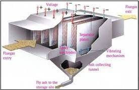
Gas Distribution tests in Electrostatic Precipitators
In order to evaluate the
uniformity of the distribution of the flue gas in an ESP, offline “Gas Distribution Test” is generally
conducted. In this test, the flue gas velocities are measured over the entire
cross section of the ESP (generally in the end of first field or in start of
second field) and then the coefficient of variation (CV) is calculated which
represent the flow variation in the ESP statically.
Test Procedure
Air flow
through the ESP chamber is established by running the ID, FD & PA air
fans at suitable loadings. Once the flow is established by preliminary
measurement, the loading of fans and furnace draught are recorded so that the
same condition can be maintained for all subsequent tests.
The velocity
measurements are made inside and across the precipitator chamber, between the
first and second field, using vane type anemometer. The measurement points are
distinctly marked on the trailing edge of the collecting electrodes of the first
field.
The vertical
space between the points is 500/1000 mm (depends upon the size of ESP) leaving
a gap of 500 mm from top and bottom of the collecting electrode. The readings
shall be taken at every alternate collecting electrode spacing.
|
Gas Distribution Test of ESP |
|
||||||||
|
|||||||||
|
Boiler
No. |
|
XYZ00N |
|
||||||
|
Boiler
Type |
|
BFBC |
|
||||||
|
Plant
capacity |
MW |
10 |
|
||||||
|
Boiler
Capacity |
TPH |
48 |
|
||||||
|
Design
Gas Flow |
M3/Sec |
26.55 |
|
||||||
|
Design
Gas Temp |
Deg. C |
140 |
|
||||||
|
ID Fan |
Speed |
RPM |
140 |
|
|||||
|
Load |
Amp |
140 |
|
||||||
|
Height (Mtr) |
Collecting plate No. |
||||||||
|
1 |
2 |
3 |
4 |
5 |
6 |
7 |
8 |
9 |
|
|
Velocity readings in M/Sec (Xi) |
|||||||||
|
0.50 |
0.5 |
0.55 |
0.45 |
0.55 |
0.48 |
0.52 |
0.43 |
0.49 |
0.33 |
|
1.00 |
0.28 |
0.35 |
0.38 |
0.41 |
0.37 |
0.46 |
0.48 |
0.45 |
0.53 |
|
1.50 |
0.32 |
0.39 |
0.52 |
0.38 |
0.52 |
0.56 |
0.46 |
0.32 |
0.34 |
|
2.00 |
0.35 |
0.53 |
0.48 |
0.54 |
0.47 |
0.47 |
0.45 |
0.47 |
0.28 |
|
2.50 |
0.28 |
0.45 |
0.45 |
0.47 |
0.4 |
0.45 |
0.39 |
0.46 |
0.32 |
|
3.00 |
0.27 |
0.27 |
0.32 |
0.35 |
0.52 |
0.44 |
0.5 |
0.47 |
0.43 |
|
3.50 |
0.28 |
0.41 |
0.48 |
0.4 |
0.53 |
0.6 |
0.52 |
0.53 |
0.45 |
|
4.00 |
0.36 |
0.56 |
0.49 |
0.42 |
0.59 |
0.53 |
0.56 |
0.45 |
0.35 |
|
4.50 |
0.6 |
0.57 |
0.55 |
0.5 |
0.5 |
0.52 |
0.57 |
0.52 |
0.52 |
|
Calculation |
|
|||
|
No. of
Reading |
n |
Nos |
81 |
|
|
Highest
Velocity |
|
M/Sec |
0.6 |
|
|
Lowest
Velocity |
|
M/Sec |
0.27 |
|
|
Average
Velocity |
X |
M/Sec |
0.45 |
|
|
Standard
Deviation |
|
0.09 |
||
|
Coefficient of Variation |
Coefficient
of Variation = (Standard
Deviation / Mean) * 100 |
% |
19.46 |
|
The test is
conducted on a trial basis and hence more than one trial may be required before
a gas distribution meeting the acceptance criteria is obtained. Adjustments if required
will be carried out based on the tests, modifying the location of
deflector/throttling plates. The above is repeated till the desired
distribution meeting the acceptance criteria is obtained.

Note: - The acceptance criterion for gas distribution is that the coefficient of variation should be less than 20 %.


Comments
Post a Comment